Home
› Furnace Low Voltage Wiring Diagram : Hvac Installation Training Basics For Condensate Safety Switches Low Voltage Wiring Drain Trap Youtube / Supervision is needed by a licensed hvacr tech while doing this as experience and apprenticeship garners wisdom and safety.
Furnace Low Voltage Wiring Diagram : Hvac Installation Training Basics For Condensate Safety Switches Low Voltage Wiring Drain Trap Youtube / Supervision is needed by a licensed hvacr tech while doing this as experience and apprenticeship garners wisdom and safety.
Furnace Low Voltage Wiring Diagram : Hvac Installation Training Basics For Condensate Safety Switches Low Voltage Wiring Drain Trap Youtube / Supervision is needed by a licensed hvacr tech while doing this as experience and apprenticeship garners wisdom and safety.. The contacts inside the fan limit control open and allows the blower to shut off. Low voltage connections if the air handler was previously installed, nothing will need to change on the low voltage wiring. I go over a schematic diagram. Lower level is heat only, so i need to run a c from furnace to thermostat to provide 24v continuity power. Color code, how it works, diagram!
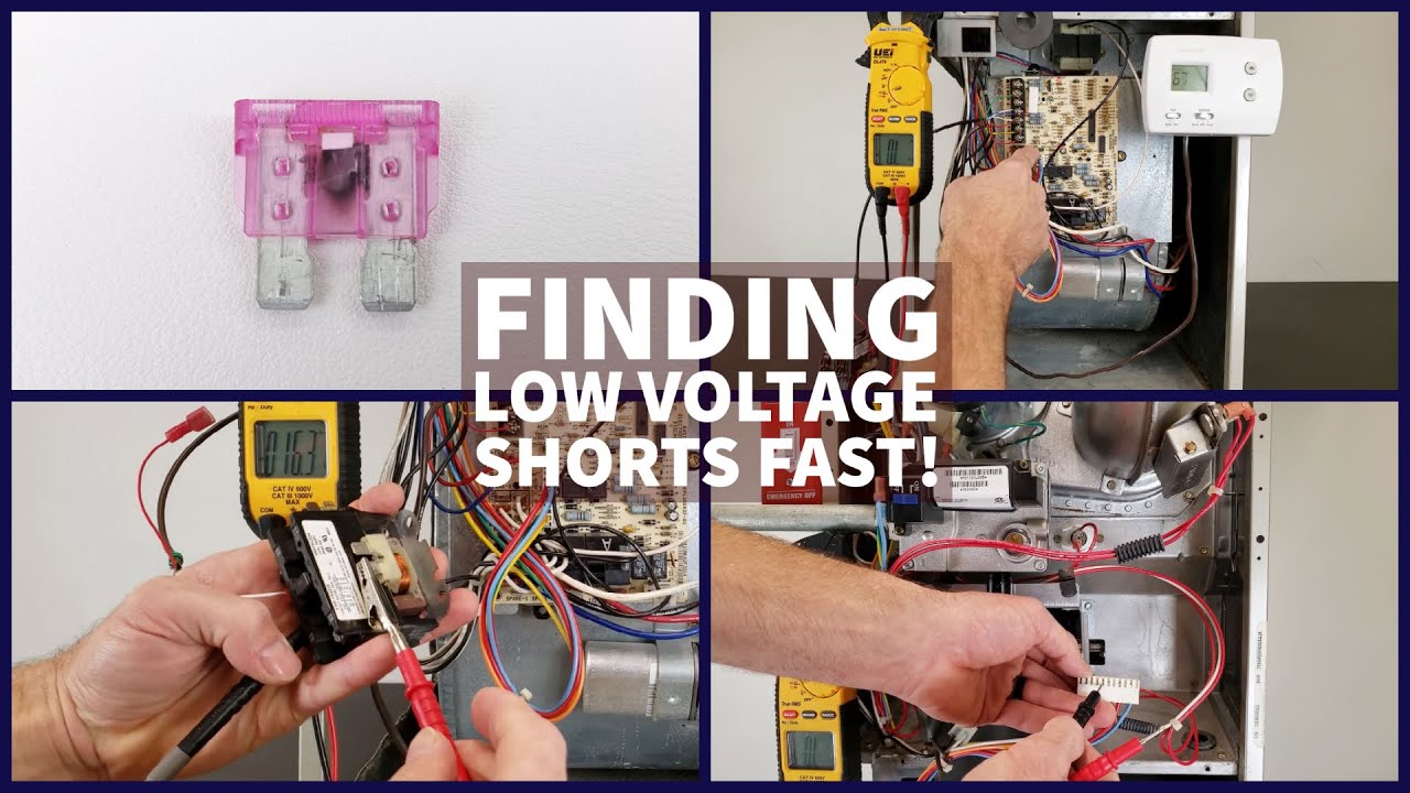
I opened the board for the furnace, located the c, tested the voltage at the board (read 27v between c and r), connected a spare 18 awg from the existing thermostat wiring to the c and ran up. There is a wiring diagram and adjacent to it a line wiring diagrams or connection diagrams include all of the devices in the system and show their physical relation to each other. Field wiring diagram for two stage thermostat and single stage furnace, outdoor unit without transformers. Most of the diagrams in this book are shown in two ways. The national electrical code nec includes many specific requirements for outdoor circuits and equipment.
Ac Low Voltage Wiring Wiring Diagram Networks from lh4.googleusercontent.com Refer to the wiring diagrams (figure 22, after the gas piping to the furnace is complete, all connections page 22 & figure 23, page 23) and the low voltage field wiring must be tested for gas leaks. Symbols that represent the constituents inside the. Unplug 16 wire low voltage harness from the motor control board. Lower level is heat only, so i need to run a c from furnace to thermostat to provide 24v continuity power. This video contains 10 wiring diagrams. Label all wires prior to disconnection when servicing controls. Also a few branch circuits. A wiring diagram is a kind of schematic which uses abstract pictorial symbols to demonstrate all the interconnections of components in a system.
In this video i show how to read or follow the wires on a gas furnace wiring diagram.
4‐ or 16‐pin connector to motor carries low‐voltage control signals. The furnace will not operate unless the polarity and ground are properly connected as shown in figure 12 or the wiring diagram label inside of the control door. How to wire an air conditioner for control 5 wires the diagram below includes the typical control wiring for a. Wiring diagrams vs line diagrams. Always follow manufacturer wiring diagrams as they will supersede these. E3 furnace low voltage wiring if installed with platinum series models. Furnace model e3h 015h thank u email protected submitted. Wiring diagrams include certain things: Goodman furnace wiring diagram jaboobie com. Low voltage wiring instructions for your home. I opened the board for the furnace, located the c, tested the voltage at the board (read 27v between c and r), connected a spare 18 awg from the existing thermostat wiring to the c and ran up. F electrical wiring diagram (system circuits). Field wiring diagram for two stage thermostat and single stage furnace, outdoor unit without transformers.
Lower level is heat only, so i need to run a c from furnace to thermostat to provide 24v continuity power. Most of the diagrams in this book are shown in two ways. They are also useful for making repairs. In this video i show how to read or follow the wires on a gas furnace wiring diagram. Low voltage wiring shall not be attached to sprinkler piping.
Control Circuits For Air Conditioning And Heating Hvac from highperformancehvac.com Label all wires prior to disconnection when servicing controls. Coil coil voltage nominal nominal. 1 thermidistat ontrol visit low voltage wiring diagrams nte: Utdoor air sensor must be attached in all dual fuel applications. Furnace model e3h 015h thank u email protected submitted. Most of the diagrams in this book are shown in two ways. I post hvac videos on topics such as refrigerant charging, furnaces, heat pumps, air conditioning, electrical troubleshooting, wiring, refrigeration cycle, superheat and subcooling, gas lines, & more! Use wiring diagrams to assist in building or manufacturing the circuit or electronic device.
4‐ or 16‐pin connector to motor carries low‐voltage control signals.
The furnace will not operate unless the polarity and ground are properly connected as shown in figure 12 or the wiring diagram label inside of the control door. E3 furnace low voltage wiring if installed with platinum series models. Three common controls used in electric furnaces are _. Low voltage wiring diagrams motherwill com. Power supply the furnace internal wiring is complete except for the power supply and the thermostat wires. Supervision is needed by a licensed hvacr tech while doing this as experience and apprenticeship garners wisdom and safety. Unplug 16 wire low voltage harness from the motor control board. I opened the board for the furnace, located the c, tested the voltage at the board (read 27v between c and r), connected a spare 18 awg from the existing thermostat wiring to the c and ran up. Furnace model e3h 015h thank u email protected submitted. Utdoor air sensor must be attached in all dual fuel applications. Low voltage wiring shall not be attached to sprinkler piping. 4‐ or 16‐pin connector to motor carries low‐voltage control signals. Low voltage wiring instructions for your home.
Resolving furnace and a/c rfi (radio frequency interference) problems: F electrical wiring diagram (system circuits). They are also useful for making repairs. Ead the entire instruction manual before starting the installation. Low voltage wiring shall not be attached to sprinkler piping.
Wiring A Heat Pump Thermostat To The Air Handler And Outdoor Unit Functions Terminals Colors Youtube from i.ytimg.com This video contains 10 wiring diagrams. F electrical wiring diagram (system circuits). Furnace model e3h 015h thank u email protected submitted. Symbols that represent the constituents inside the. The contacts inside the fan limit control open and allows the blower to shut off. Label all wires prior to disconnection when servicing controls. The circuit diagram for this design can be seen below: 4‐ or 16‐pin connector to motor carries low‐voltage control signals.
Lower level is heat only, so i need to run a c from furnace to thermostat to provide 24v continuity power.
The original diagram can be witnessed in the following image for the induction heater coil l1, many 1mm copper wire may be wound in parallel or in bifilar manner in order to dissipate current more effectively causing lower heat generation in the coil. Most of the diagrams in this book are shown in two ways. This video contains 10 wiring diagrams. Refer to the wiring diagrams (figure 22, after the gas piping to the furnace is complete, all connections page 22 & figure 23, page 23) and the low voltage field wiring must be tested for gas leaks. How to read a furnace wiring diagram. Wiring diagrams include certain things: If there was a short line cord to the furnace blower motor, rather than a 'long' wiring harness, the radiated. The national electrical code nec includes many specific requirements for outdoor circuits and equipment. F electrical wiring diagram (system circuits). Coil coil voltage nominal nominal. Two types of wiring diagrams used in this field are _. The voltage should be measured at 13.06.2019 · furnace low voltage wiring. Wiring diagram 5 wire heatingcooling thermostat figure 4 4 9.