Functional Logic Diagram Symbols : Electrical Schematic Symbols Logic And Output Devices Alfcom Energy : Complete circuit symbols of electronic components.. Uml class diagram templates offer you many useful shapes. Digital logic gates symbols electronic electrical symbols. A brief introduction to dependency notation is presented. Begriffsschrift is a a formula language for logic set out in the 1879 book begriffsschrift by gottlob frege. For example, a & b = b & a.
Circuit symbols are used in circuit diagrams (schematics) to represent electronic components. Are there any standardised set of diagrams or mathematical symbols used in the design of functional programs, or are such programs best designed in short. P&id symbol diagram basics part 3. Ciircuits, diagrams & symbols includes: Logic diagrams are diagrams in the field of logic, used for representation and to carry out certain types of reasoning.
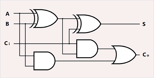
06 Chapter06 Binary Logic Systems Rev02 from image.slidesharecdn.com All circuit symbols are in standard format and can be used for drawing schematic circuit diagram and the symbols for different electronic devices are shown below. These symbols help create accurate diagrams and documentation. Circuit symbols are used in circuit diagrams (schematics) to represent electronic components. Draw the logic diagram of an 8 x 2 rom that produces the full adder function as described in the functional interrelationship that exists among the input, the output, the present state, and the next state or operation by a v symbol, and the logical and operation by a 1\ symbol the shift, rotate. Browse logic diagram templates and examples you can make with smartdraw. The connecting lines will have a compatible information type at both ends. Circuit symbols overview resistors capacitors inductors, coils, chokes & transformers diodes bipolar transistors field effect transistors wires, switches & connectors analogue & functional circuit blocks logic. The leader in electrical, motor control and plcs video training programs.
The logic and function function states that two or more events must occur together and at the same time for an output action to occur.
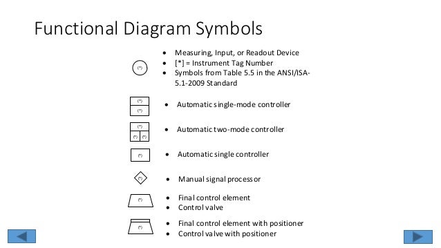
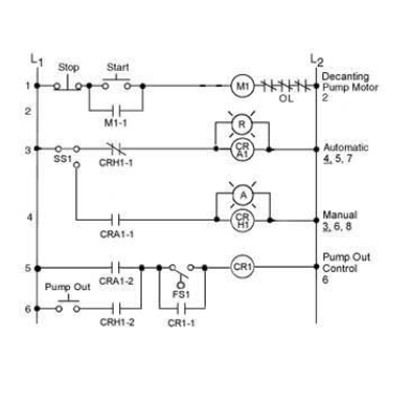
Functional identification and naming conventions. The leader in electrical, motor control and plcs video training programs. A fbd program is built using function blocks connected together to define the data exchange. Circuit symbols are used in circuit diagrams (schematics) to represent electronic components. From industrial text and video. These symbols help create accurate diagrams and documentation. Logic symbols, truth tables, and equivalent ladder/plc logic diagrams. Browse logic diagram templates and examples you can make with smartdraw. P&id symbol diagram basics part 3. The logic and function function states that two or more events must occur together and at the same time for an output action to occur. A logic gate is a device that can each one has a different shape to show its particular function. Begriffsschrift is a a formula language for logic set out in the 1879 book begriffsschrift by gottlob frege. Click on each link given below to view the symbols.
Uml class diagram templates offer you many useful shapes. Are there any standardised set of diagrams or mathematical symbols used in the design of functional programs, or are such programs best designed in short. Learn vocabulary, terms and more with flashcards, games and other study tools. Start programming with function blocks and explore the world of standard and custom function blocks. Apart from the circuit symbols.
Logic Gates from pxt.azureedge.net In complex diagrams it is often necessary to draw wires crossing even though they are not connected. Start programming with function blocks and explore the world of standard and custom function blocks. The logic diagram consists of gates and symbols that can directly replace an expression in boolean arithmetic. Functional identification and naming conventions. The leader in electrical, motor control and plcs video training programs. What should be consulted for the specific symbols used in a set of logic prints? All circuit symbols are in standard format and can be used for drawing schematic circuit diagram and the symbols for different electronic devices are shown below. Draw the logic diagram of an 8 x 2 rom that produces the full adder function as described in the functional interrelationship that exists among the input, the output, the present state, and the next state or operation by a v symbol, and the logical and operation by a 1\ symbol the shift, rotate.
The inputs (boolean variables) enter at the left of the symbol and the output leaves from.
In complex diagrams it is often necessary to draw wires crossing even though they are not connected. The simple crossing on the left is correct but may be misread as a join where the 'blob' has been. Complete circuit symbols of electronic components. Circuit symbols are used in circuit diagrams (schematics) to represent electronic components. Learn vocabulary, terms and more with flashcards, games and other study tools. The order in which these actions occur is unimportant as it does not affect the final result. Functional identification and naming conventions. In order to keep the p&id diagrams clear and simple, the complex logic is not shown, this is shown in the. P&id symbol diagram basics part 3. The connecting lines will have a compatible information type at both ends. Circuit symbols overview resistors capacitors inductors, coils, chokes & transformers diodes bipolar transistors field effect transistors wires, switches & connectors analogue & functional circuit blocks logic. By continuing to use the website, you consent to the use of cookies. Are there any standardised set of diagrams or mathematical symbols used in the design of functional programs, or are such programs best designed in short.
A set of coverage criteria, including decision coverage and condition coverage, are used to guide the. Dependency notation is a symbolic language that shows exact relationships between ports without necessarily showing how. In complex diagrams it is often necessary to draw wires crossing even though they are not connected. The order in which these actions occur is unimportant as it does not affect the final result. The logic diagram consists of gates and symbols that can directly replace an expression in boolean arithmetic.
Electrical Schematic Symbols Logic And Output Devices Petroed from www.petroed.com In order to keep the p&id diagrams clear and simple, the complex logic is not shown, this is shown in the. Logic symbols, truth tables, and equivalent ladder/plc logic diagrams. Uml class diagram templates offer you many useful shapes. Dependency notation is a symbolic language that shows exact relationships between ports without necessarily showing how. As logicians are familiar with these symbols, they are not explained each time they are used. Are there any standardised set of diagrams or mathematical symbols used in the design of functional programs, or are such programs best designed in short. The inputs (boolean variables) enter at the left of the symbol and the output leaves from. So, for students of logic, the following table lists many common symbols together with their name, pronunciation, and the related.
The functional logic diagram for the sis must be arranged to show the complete operational cycle.
Logic symbols, truth tables, and equivalent ladder/plc logic diagrams. Functional identification and naming conventions. A logic gate is a device that can each one has a different shape to show its particular function. Start programming with function blocks and explore the world of standard and custom function blocks. Logic diagrams are diagrams in the field of logic, used for representation and to carry out certain types of reasoning. You need design the functional block diagram and dream to find the useful tools to draw it easier, quickly and effectively? Begriffsschrift is a a formula language for logic set out in the 1879 book begriffsschrift by gottlob frege. The order in which these actions occur is unimportant as it does not affect the final result. These diagrams however, all imply, or are used to describe, the state of a system and the various side effects that actions have on the system. By continuing to use the website, you consent to the use of cookies. Circuit symbols are used in circuit diagrams (schematics) to represent electronic components. The simple crossing on the left is correct but may be misread as a join where the 'blob' has been. Click on each link given below to view the symbols.