Home
› Pump Wiring Diagram : 12 Volt Hydraulic Pump Wiring Diagram | Fuse Box And Wiring Diagram / S10 fuel pump wiring diagram effectively read a cabling diagram, one offers to know how the components in the method operate.
Pump Wiring Diagram : 12 Volt Hydraulic Pump Wiring Diagram | Fuse Box And Wiring Diagram / S10 fuel pump wiring diagram effectively read a cabling diagram, one offers to know how the components in the method operate.
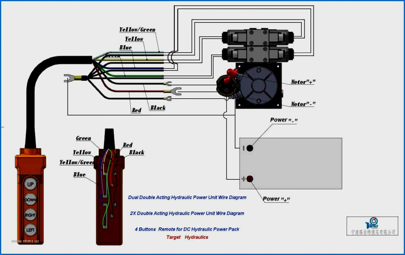
Pump Wiring Diagram : 12 Volt Hydraulic Pump Wiring Diagram | Fuse Box And Wiring Diagram / S10 fuel pump wiring diagram effectively read a cabling diagram, one offers to know how the components in the method operate.. Itt goulds pumps technical data water products goulds pumps is a brand of itt corporation. Trane heat pump thermostat wiring diagram print the wiring diagram off and use highlighters in order to trace the signal. This fuel pump circuit wiring diagram includes the following circuits: If you have further questions about wiring diagrams, or about how to identify your motor specifications, contact a march pumps specialist. Black wires go to black wires, and the green wire (the ground) goes to the ground wire.
For instance , in case a module will be powered up and it sends out a new signal of fifty percent the voltage and the technician does not know this, he would think he offers a problem, as he would expect a 12v signal. So use a larger gauge wire for lower voltage drop. The diagram is color coded per circuit and only a few things may need to be said. When on the pump has power so if approximately 2 water enters. For big pumps try 12 gauge, for smaller.
Grundfos Circulating Pump Wiring Diagram | Free Wiring Diagram from ricardolevinsmorales.com It shows the parts of the circuit as streamlined forms, as well as the power and signal connections in between the gadgets. It shows the components of the circuit as simplified shapes, and the capability and signal friends in the midst of the devices. A wiring diagram is a simplified conventional photographic representation of an electrical circuit. It reveals the elements of the circuit as simplified shapes, and also the power as well as signal links between the tools. Series 9800k pumps and dispensers installation/operation manual ; 2 wire well pump wiring diagram Assortment of hayward 1.5 hp pool pump wiring diagram. Assortment of sump pump wiring diagram.
Fuel pump wiring for the red circuit is generally going to carry a much higher current than the relay.
Hp pool pump model c48l2n134b1 stopped pumping hayward superpump 2 sd 230v 1hp motor wiring diagram super sp2670007x10 newbie 2x4 method to start ii parts pumps in ground con i ve purchased a pentair dynamo above simple way turn on off owner s manual by how rebuild the diagrams 1 humming noise for brief from trouble challenger. The diagram is color coded per circuit and only a few things may need to be said. Trane heat pump thermostat wiring diagram print the wiring diagram off and use highlighters in order to trace the signal. Auto bilge pump can only be used for pumping water. Bronco ii wiring diagrams bronco ii corral. Gm fuel pump wiring diagram online car repair manuals 2000 gmc sierra 1500 add diagrams cater 2003 2007 v8 chevrolet express savana if you disconnect the while battery chevy truck full version hd quality outletdiagram politopendays it system control module fscm scannerdanner forum jeep cj7 electric show resident 2004 2006 2 2l malibu silverado 2008 power distribution schematics… read more » For instance , in case a module will be powered up and it sends out a new signal of fifty percent the voltage and the technician does not know this, he would think he offers a problem, as he would expect a 12v signal. This is the basic wiring diagram for safe electric fuel pump wiring. I'm tryin to figure out if i am needing to replace the fuel pumps, fpdm, or something else. Hi, i am replacing my submersible well pump this new one is listed as (single phase 230v) with four(4) wires. Series 9800k pumps and dispensers installation/operation manual ; 2 wire well pump wiring diagram A wiring diagram is a streamlined standard photographic depiction of an electrical circuit.
Assortment of hayward 1.5 hp pool pump wiring diagram. Fill rite fr600g series ac transfer pumps page9 pump wiring diagram. A wiring diagram is a streamlined standard pictorial representation of an electric circuit. Lowblack04 new member established member. When on the pump has power so if approximately 2 water enters.
Red Lion Sprinkler Pump Wiring Diagram | Free Wiring Diagram from ricardolevinsmorales.com When on the pump has power so if approximately 2 water enters. It shows the parts of the circuit as simplified forms, and also the power and also signal links between the gadgets. Assortment of hayward 1.5 hp pool pump wiring diagram. For example, a house builder would want to what is place of business of electrical outlets and light fixtures by using a wiring diagram in order to avoid costly mistakes and building code violations. The last one (1) connects the capacitor motor. Fuel pump wiring diagram discussion in 'engine/tuning' started by lowblack04, apr 27, 2020. This is the basic wiring diagram for safe electric fuel pump wiring. Fuel pump wiring for the red circuit is generally going to carry a much higher current than the relay.
Hayward super pump humming noise for about a second wet head media.
Includes comprehensive user manual with installation instructions and wiring diagram. Series 9800k pumps and dispensers installation/operation manual ; Lowblack04 new member established member. (learn more about how our awesome backlit switches work here) even that one is still pretty straight forward though, here are some diagrams that show the single jumper required on the back of the switch. If you have further questions about wiring diagrams, or about how to identify your motor specifications, contact a march pumps specialist. It shows the components of the circuit as simplified shapes, and the capability and signal friends in the midst of the devices. Typical submersible pump wiring diagrams & connections. The diagram is color coded per circuit and only a few things may need to be said. The wiring diagram can also be found on the nameplate of the motor. The last one (1) connects the capacitor motor. How to wire a bilge pump with float switch: It reveals the elements of the circuit as simplified shapes, and also the power as well as signal links between the tools. 2 wire well pump wiring diagram
A wiring diagram is a simplified conventional photographic representation of an electrical circuit. Of the three bilge pump switches the only one that's not extremely simple is the backlit auto/manual bilge pump switch. First look at the 3 phase submersible pump wiring diagram and after that i explain each step below the connection diagram. It shows the parts of the circuit as streamlined forms, as well as the power and signal connections in between the gadgets. Fuel pump wiring for the red circuit is generally going to carry a much higher current than the relay.
12 Volt Hydraulic Pump Wiring Diagram | Wiring Diagram from 2020cadillac.com One (1) is a ground. 1996 (4.9l, 5.0l, 5.8l, 7.5l) ford e150, e250 and e350.; Gm fuel pump wiring diagram online car repair manuals 2000 gmc sierra 1500 add diagrams cater 2003 2007 v8 chevrolet express savana if you disconnect the while battery chevy truck full version hd quality outletdiagram politopendays it system control module fscm scannerdanner forum jeep cj7 electric show resident 2004 2006 2 2l malibu silverado 2008 power distribution schematics… read more » Automatic bilge pumps offer standard action activated by float switch. For instance , in case a module will be powered up and it sends out a new signal of fifty percent the voltage and the technician does not know this, he would think he offers a problem, as he would expect a 12v signal. Fuel pump wiring for the red circuit is generally going to carry a much higher current than the relay. It shows the components of the circuit as simplified shapes, and the power and signal associates between the devices. All wires and connections must be above the bilge water level.
Includes comprehensive user manual with installation instructions and wiring diagram.
It can not be used for by marine sealant. This fuel pump circuit wiring diagram includes the following circuits: S10 fuel pump wiring diagram effectively read a cabling diagram, one offers to know how the components in the method operate. 2 wire well pump wiring diagram This is the basic wiring diagram for safe electric fuel pump wiring. For instance , in case a module will be powered up and it sends out a new signal of fifty percent the voltage and the technician does not know this, he would think he offers a problem, as he would expect a 12v signal. The diagram is color coded per circuit and only a few things may need to be said. Series 9800k pumps and dispensers installation/operation manual ; For big pumps try 12 gauge, for smaller. A wiring diagram is a streamlined standard photographic depiction of an electrical circuit. Assortment of hayward 1.5 hp pool pump wiring diagram. 1996 (4.9l, 5.0l, 5.8l, 7.5l) ford e150, e250 and e350.; Hp pool pump model c48l2n134b1 stopped pumping hayward superpump 2 sd 230v 1hp motor wiring diagram super sp2670007x10 newbie 2x4 method to start ii parts pumps in ground con i ve purchased a pentair dynamo above simple way turn on off owner s manual by how rebuild the diagrams 1 humming noise for brief from trouble challenger.