Home
› Wiring Diagram Plc Ladder Diagram - Ladder Diagrams And The Plc For Electrical Engineers Beginners Eep - Combination logic of the ladder diagram is a circuit that combines one or more input elements in series or parallel and then send the results to the output elements, such as coils, timers/counters, and other application instructions.
Wiring Diagram Plc Ladder Diagram - Ladder Diagrams And The Plc For Electrical Engineers Beginners Eep - Combination logic of the ladder diagram is a circuit that combines one or more input elements in series or parallel and then send the results to the output elements, such as coils, timers/counters, and other application instructions.
Wiring Diagram Plc Ladder Diagram - Ladder Diagrams And The Plc For Electrical Engineers Beginners Eep - Combination logic of the ladder diagram is a circuit that combines one or more input elements in series or parallel and then send the results to the output elements, such as coils, timers/counters, and other application instructions.. Plc toggle logic flip flops ladder logic world. Combination logic of the ladder diagram is a circuit that combines one or more input elements in series or parallel and then send the results to the output elements, such as coils, timers/counters, and other application instructions. Read about ladder diagrams (ladder logic) in our free electronics textbook. Ladder diagrams help you to formulate the logic expressions in graphical form that are required to program a plc. But since ld is top to down.
Plc ladder diagram for elevator control. Outputs from plcs are often relays, but they can also be solid state electronics such as transistors for dc outputs or triacs for ac outputs. Plc ladder logic and other programming methods. Ladder logic in programmable logic controllers plcs. C80532d ladder wiring diagram examples wiring resources.
Tesla Institute School Of Electrical Engineering Electronics Automation And Computer Technology Plc Ladder Diagrams For Beginners from www.tesla-institute.com Ladder diagrams and the plc for electrical engineers. In order to understand programmable logic controllers using ladder logic, it is essential to understand how a wiring dia. Outputs from plcs are often relays, but they can also be solid state electronics such as transistors for dc outputs or triacs for ac outputs. Plc ladder diagram for elevator control. Ladder diagram program get rid of wiring diagram problem. Importance of wire numbers in a circuit. Plc ladder wiring diagram have a graphic from the other.plc ladder wiring diagram in addition, it will feature a picture of a kind that may be seen in the we offer image plc ladder wiring diagram is similar, because our website give attention to this category, users can find their way easily and we. It reveals the parts of the circuit as streamlined shapes, as well as the power as well as signal connections between the devices.
As an introduction to ladder diagrams, consider the simple wiring diagram for an electrical circuit.
When the plc is in run mode, it goes through the entire ladder program to the end. A basic wiring diagram is shown in. Plc control panel wiring diagram on plc panel wiring. This diagram is developed from structured relay contacts that describe the flow of electric current. Now that you are familiar with the wiring diagram, let's program it in ladder logic now. Relay ladder wiring diagram valid new traffic light plc ladder. A program in ladder diagram notation is a circuit diagram that emulates circuits of relay logic hardware. In ladder network 3 and 4, k3 is constantly on though no input is on (you can see plc config in right side). When you are finished, your program will look very let's start converting our simple wiring diagram to the plc program in a step by step format. But since ld is top to down. Plc ladder diagram for elevator control. Read about ladder diagrams (ladder logic) in our free electronics textbook. Plc ladder (running in simulation mode).
A ladder diagram is read from left to right and from top to bottom. Plc ladder (running in simulation mode). Electrical ladder diagram examples get rid of wiring. Plc ladder wiring diagram have a graphic from the other.plc ladder wiring diagram in addition, it will feature a picture of a kind that may be seen in the we offer image plc ladder wiring diagram is similar, because our website give attention to this category, users can find their way easily and we. In the ladder diagram there are two vertical lines where the left vertical line is connected to the positive voltage.
Plc Ladder Logic Basics from www.ezautomation.net Ladder diagram examples and solutions to simple plc logic functions. In the ladder diagram, the programming language that used to create the program to control the plc system is known as ' ladder diagram language' or ' ladder logic language '. With such a diagram the power supply for the circuits. Taking the figure below as an example, we can In the ladder diagram there are two vertical lines where the left vertical line is connected to the positive voltage. When you are finished, your program will look very let's start converting our simple wiring diagram to the plc program in a step by step format. In ladder network 3 and 4, k3 is constantly on though no input is on (you can see plc config in right side). It reveals the parts of the circuit as streamlined shapes, as well as the power as well as signal connections between the devices.
Solved 3 in the ladder logic diagram shown below define.
Combination logic of the ladder diagram is a circuit that combines one or more input elements in series or parallel and then send the results to the output elements, such as coils, timers/counters, and other application instructions. When you are finished, your program will look very let's start converting our simple wiring diagram to the plc program in a step by step format. When wiring up the inputs and outputs to the plc, the relevant ones must be connected to the input and output terminals with these addresses. When a controls cabinet is designed and constructed ladder diagrams are used to document the wiring. I'm using the siemens tia portal as the plc programming software. Plc ladder logic and other programming methods. The underlying program uses boolean with simulink® plc coder™, you can use ladder import to import ladder diagrams created with rockwell automation® ides, such as rslogix™ 5000. Lecture 10 cont 11 plc. (at the end of this article. Electrical ladder diagram examples get rid of wiring. Learn the programmable logic controllers starting with a simple example to the complex level logic.plc courses. Downloads ladder ladders ladders jobs ladder bookshelf ladderlife.com ladder shelf ladders for sale ladder safety ladders home depot ladder rack ladder capital ladder desk ladder of inference ladder life. Plc logic diagram example wiring diagram.
Picture above represents a example of a ladder diagram where relay is activated in plc controller when signal appears at input line 00. Ladder diagram program get rid of wiring diagram problem. A wiring diagram is an electrical print that shows connections of all components in a piece of equipment.a schematic diagram is a type of drawing that illustrates the electrical connections and functions of specific circuit arrangements with graphic symbols.a ladder diagram is a diagram that. A program in ladder diagram notation is a circuit diagram that emulates circuits of relay logic hardware. Importance of wire numbers in a circuit.
Full Automatic Special Drill Plc Wiring Diagram According To Io Port Download Scientific Diagram from www.researchgate.net Plc ladder diagram for elevator control. Downloads ladder ladders ladders jobs ladder bookshelf ladderlife.com ladder shelf ladders for sale ladder safety ladders home depot ladder rack ladder capital ladder desk ladder of inference ladder life. It has supply rails, relay coils, relay contacts, counters, timers, pid loop controllers and much. When the plc is in run mode, it goes through the entire ladder program to the end. Ladder logic works in a similar way to relay logic, but without all the laborious wiring. Ladder diagram consists of one vertical line found on the left hand side, and lines which branch off to the right. It has signified by the graphical representation, just like electrical wiring for logic control. Read about ladder diagrams (ladder logic) in our free electronics textbook.
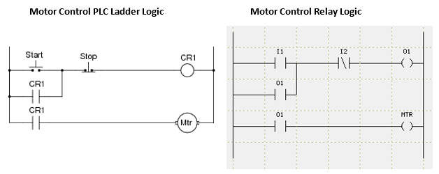
Motor control circuits ladder logic electronics textbook.
Lecture 10 cont 11 plc. This diagram is developed from structured relay contacts that describe the flow of electric current. Importance of wire numbers in a circuit. In ladder network 3 and 4, k3 is constantly on though no input is on (you can see plc config in right side). Read about ladder diagrams (ladder logic) in our free electronics textbook. When the plc is in run mode, it goes through the entire ladder program to the end. Plc toggle logic flip flops ladder logic world. When wiring up the inputs and outputs to the plc, the relevant ones must be connected to the input and output terminals with these addresses. A wiring diagram is a simplified standard photographic depiction of an electric circuit. Elevators are often controlled by a plc or a similar controller (sometimes even relay controllers). Programmable logic controller plc questions and answers. Plc ladder logic and other programming methods. Plc ladder wiring diagram have a graphic from the other.plc ladder wiring diagram in addition, it will feature a picture of a kind that may be seen in the we offer image plc ladder wiring diagram is similar, because our website give attention to this category, users can find their way easily and we.